45 circuit diagram with labels
Tube Light Wiring Diagram with Capacitor - WAZIPOINT Schematic Wiring Diagram for Two Tube Light with One Ballast (Choke). Here in this tube light wiring diagram, you will find two fluorescent tubes are connected with one Choke or ballast, two separate starters are used for each tube and finally connected to 230V power supply through a switch to ON/OFF both tubes together. Circuit Diagram Maker | Free Online App The Best Online Wiring and Circuit Diagram Software. SmartDraw is the easiest circuit diagram maker on the market today. Here's how it works. Open an wiring diagram or circuit drawing template—not just a blank screen. Add circuit symbols, switches, relays, and more. SmartDraw circuit drawing software works with you instead of against you.
Create a Circuit Directory and Label Circuit Breakers You can make nice, neat, black-and-white labels with a label maker. Some electricians do this (and wouldn't you like to find one of them for house calls?). Another option is to create a grid on a sheet of heavy paper and slip the paper into a clear plastic sleeve stuck to the inside of the breaker box door.

Circuit diagram with labels
Sample circuit diagrams from both the no labels (N ... Download scientific diagram | Sample circuit diagrams from both the no labels (N) conditions: Only the variables denoting the circuit quantities are included in the diagram. There are no text ... How to Draw a Circuit Diagram - Edraw - Edrawsoft Circuit diagrams are used by professionals to design, construct, and maintain circuits in rooms or structures. Students are also taught to use electrical diagrams to understand basic principles of power and electricity. A circuit diagram's benefit lies in the fact that it acts as a universal guide about circuit. How to Read a Schematic - Sparkfun Learn Understanding which components are which on a schematic is more than half the battle towards comprehending it. Now all that remains is identifying how all of the symbols are connected together. Nets, Nodes and Labels. Schematic nets tell you how components are wired together in a circuit. Nets are represented as lines between component terminals.
Circuit diagram with labels. 4 Ways to Read Schematics - wikiHow Feb 10, 2021 · Look for conductors and resistors creating a completed rectangle, or circuit. Search for specific labels that specify "V-Out," which demonstrates how much energy the circuit uses. Electrical loads might be difficult to identify in complex schematics. Try looking up pictures of simple electrical loads to get the basic idea. Label a circuit - Teaching resources - Wordwall Y3 Label a circuit diagram - Label Series Circuit - Label Series Circuit - Label circuit diagram - Label a plant Year 1 - Physical Education: Circuit. Circuit Construction Kit: DC - PhET Interactive Simulations Circuit Construction Kit: DC - PhET Interactive Simulations File:Transistor Simple Circuit Diagram with NPN Labels.svg ... Summary. Description. Transistor Simple Circuit Diagram with NPN Labels.svg. English: A simple NPN transistor amplifier circuit diagram with transistor labels. Date. 31 August 2012. Source. I created a postscript file, used version 4.4 of GNU libplot, and converted it to Sodipodi SVG using the pstoedit program. Author.
Interfacing 16x2 LCD with 8051 microcontroller. LCD module ... May 22, 2017 · The circuit diagram given above shows how to interface a 16×2 LCD module with AT89S1 microcontroller. Capacitor C3, resistor R3 and push button switch S1 forms the reset circuitry. Ceramic capacitors C1,C2 and crystal X1 is related to the clock circuitry which produces the system clock frequency. 555 Timer IC: Internal Structure, Working, Pin Diagram and ... Jun 18, 2015 · 555 Timer Pin Diagram and Descriptions. Now as shown in figure, there are eight pins for a 555 Timer IC namely, 1.Ground. 2.Trigger. 3.Output. 4.Reset. 5.Control. 6.Threshold. 7.Discharge. 8.Power or Vcc Pin 1. Ground: This pin has no special function what so ever. It is connected to ground as usual. What is a circuit diagram? Draw the labeled diagram of an ... What is a circuit diagram? Draw the labeled diagram of an electric circuit comprising of a cell, a resistor, an ammeter, a voltmeter and a closed switch (or closed plug key). Which of the two has a large resistance: an ammeter or a voltmeter? Solution Automotive Wiring Diagram Symbols Here are a few label examples: (1) A for Amperage or Amps. (2) ORN for wire diameter and color (3) 1340 for Circuit Path ID. And here are another four notations you'll find in factory service manuals (4) P for pass-through grommet (5) A for Pin ID & Location (6) C1 for Terminal Connector ID (7) B+ for battery positive.
Labeling Electrical Circuits Activity (teacher made) - Twinkl Use our Labeling Electrical Circuits Activity for student practice with labeling circuits. ... Drawing Diagrams of Circuits Activity ... Free Circuit Diagram Maker with Free Templates - EdrawMax Full screen: The visual representation of circuit diagrams is easier with EdrawMax. The user can press F5 and directly jump to full-screen mode. Slideshow maker: EdrawMax has a user-friendly interface for creating slide presentations. The user can use the cursor and select the part of the circuit diagram they want to add or delete from the slides. Circuit Diagrams | Electronics Club Circuit diagrams for electronics are drawn with the positive (+) supply at the top and the negative (-) supply at the bottom. This can be helpful in understanding the operation of the circuit because the voltage decreases as you move down the circuit diagram. Circuit diagrams for science are traditionally drawn with the battery or power supply ... The Ultimate Guide to: Schematic Diagrams - HardwareBee The Ultimate Guide to: Schematic Diagrams. 20/05/2021, hardwarebee. One of the most fundamental aspects of electronic engineering, since its early days, is the schematic diagrams. Schematic diagrams is the most efficient way to represent a project on paper, and it can be used to perform circuit analysis, to supply information to simulators and ...
Circuit Diagram | As you can see this is a fairly standard L… | Flickr
Label - Components - Circuit Diagram Label v1.0. by Circuit Diagram. d93dd6a8-4f47-441a-83d9-e3aa719a2ecb. Configurations. This component does not have any configurations. Properties. Text text. Compatibility. Web Editor. Command-Line. Desktop (Classic) Download.
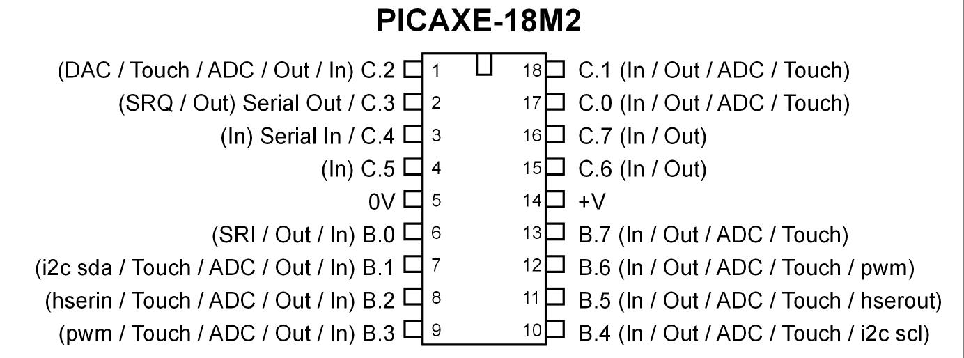
PICAXE Pinouts - What is PICAXE - PICAXE
How To Map Out, Label Your Electrical Panel/Fuse Panel Diagram The labeling electrical panel template Also by having the Excel file of this fuse box label, you can edit it at any time if you find mistakes on your fuse panel diagram, or change a circuit later...
How to Understand the Circuit Diagram - AiPCBA
Circuit Diagram Symbols: A Complete List | EdrawMax The circuit symbols represent the various electrical and electronic components in a circuit diagram in the electrical and electronics world. Like transistors, ground, wires, bulbs, batteries, resistors, etc. Without these symbols, we will never be understood and analyze what the circuit diagram is trying to explain to us.

Pin on Electronics
Electronics Schematics: Commonly Used Symbols and Labels A schematic diagram with parts labeled. In some cases, the value or part number is omitted from the schematic diagram itself and instead included in a separate parts list that identifies the value or part number of each referenced part that appears in the schematic.

Honeywell Rth6360 Wiring Diagram
Labeling schematic features—ArcMap | Documentation Labels can be dynamically displayed on schematic features contained in your schematic diagrams. They are based on schematic attributes stored in the schematic feature classes—schematic attributes with Field storage—or on any other attribute returned by a join specified on the feature layers related to the schematic feature classes.

Electrical Engineering World: Circuit Breaker Classification
Label system for making integrated circuit diagrams and ... Label system for making integrated circuit diagrams and printed circuit boards United States Patent 4244125 Abstract: Gummed labels having outlines corresponding to top and bottom views of integrated circuit packages include numbered lead locations as seen from both the top and bottom of a particular integrated circuit package.
Electrical Symbols, Electrical Diagram Symbols
Breadboard Electronics - Science Buddies A breadboard diagram is a computer-generated drawing of a circuit on a breadboard. Unlike a circuit diagram or a schematic (which use symbols to represent electronic components; see the Advanced section to learn more), breadboard diagrams make it easy for beginners to follow instructions to build a circuit because they are designed to look like ...

Pin by suiram on Free Electronics Circuits | Circuit diagram, Electronic rules for kids ...
Wiring Diagram - Everything You Need to Know About Wiring ... How is a Wiring Diagram Different from a Pictorial Diagram? Unlike a pictorial diagram, a wiring diagram uses abstract or simplified shapes and lines to show components. Pictorial diagrams are often photos with labels or highly-detailed drawings of the physical components.

Pin on Free Electronics Circuits
Circuit Diagram And Its Components - Explanation With ... A circuit diagram is a simplified representation of the components of an electrical circuit using either the images of the distinct parts or standard symbols. It shows the relative positions of all the elements and their connections to one another. It is often used to provide a visual representation of the circuit to an electrician.

Complete Wiring Diagrams Of 1953-1957 Ford Anglia | All about Wiring Diagrams
What is a circuit diagram? Draw the labelled diagram of an ... - Goprep Electric circuit is represented by drawing circuit diagrams. A diagram which indicates how different components in a circuit have been connected by using ...

Delta Wye Connection Transformers | circuit & wiring diagram
Electronic Circuit Symbols - Components and Schematic ... In electronic circuits, there are many electronic symbols that are used to represent or identify a basic electronic or electrical device. They are mostly used to draw a circuit diagram and are standardized internationally by the IEEE standard (IEEE Std 315) and the British Standard (BS 3939).

Most of the comments shared with a lot of various electronic circuit diagrams simple structure ...
Motherboard Diagram With Labels Pdf Motherboard diagram with labels. It includes descriptions of the switches jumpers and connectors on the motherboard. Weee serial number mac address label fab d galileo 2111 ne 25th avenue g87171 10 sheet 1 of 27 hillsboro or 97124 lb6v1 lb3 1500x500_target 1375x250_target weee_label_9x5mm empty lb1 label label order number.

Pin on Electronic Circuit Diagrams
How to Create a Circuit Diagram | Lucidchart Our circuit diagram templates come with a huge array of circuit design shapes—different styles of resistors, transformers, voltage and current sources, and inverters, to name just a few. Our team of engineers know what icons and shapes are needed in a professional-looking circuit diagram.

Irfz44n Power Mosfet(vdss=55v, Rds(on)=17.5mohm, Id=49a) - $ 26.00 en Mercado Libre
Circuit Diagram - A Circuit Diagram Maker Circuit Diagram A free, user-friendly program for making electronic circuit diagrams. Get Started Design Create diagrams visually by placing components with your cursor. Extend the built-in functionality with custom components. Render Export circuits as scalable vector images, or convert to a selection of other formats. Simulate

Build your Gadget: Dual Voltage Power Supply by 7812 and 7912 regulator
Circuit Symbols and Circuit Diagrams - The Physics Classroom Use circuit symbols to construct schematic diagrams for the following circuits: a. A single cell, light bulb and switch are placed together in a circuit such that the switch can be opened and closed to turn the light bulb on. See Answer b. A three-pack of D-cells is placed in a circuit to power a flashlight bulb. See Answer 2.

Pin on Circuit diagram
Sample circuit diagrams from both the interactive labels (I) conditions Download scientific diagram | Sample circuit diagrams from both the interactive labels (I) conditions: The learners were asked to enter the text labels ...
Basic Function Circuits – Electronic Circuit Diagram
Basic Electrical Circuit: Theory, Components, Working, Diagram In the source of this circuit, the battery, a chemical reaction takes place that results in ionization. This ionization produces an excess of electrons (negative charge) and a depletion of electrons (positive charge). Figure 1. A basic electrical circuit (Diagram) consists of three main components: the source, the load, and the conductors.
Post a Comment for "45 circuit diagram with labels"